顶点数据的处理
本章简要介绍Sepc中顶点处理的固定功能,同时介绍应用程序图形管线如何将数据映射到顶点着色器。
绑定(Binding) 和 位置(Location)
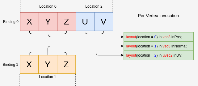
binding与顶点缓冲区中的一个位置相关联,当调用vkCmdDraw*时,顶点着色器将从该位置开始读取数据,更改bindings不需要修改顶点着色器的代码。
下面是示例代码与bindings示例图:
// Using the same buffer for both bindings in this example
VkBuffer buffers[] = { vertex_buffer, vertex_buffer };
VkDeviceSize offsets[] = { 8, 0 };

vkCmdBindVertexBuffers(
                        my_command_buffer, // commandBuffer
                        0,                 // firstBinding
                        2,                 // bindingCount
                        buffers,           // pBuffers
                        offsets,           // pOffsets
                      );
下面举例根据输入数据设置binding和location的几种方法。
示例 A - 打包数据
每个顶点的属性数据:
struct Vertex {
    float   x, y, z;
    uint8_t u, v;
};
管线创建信息:
const VkVertexInputBindingDescription binding = {
    0,                          // binding
    sizeof(Vertex),             // stride
    VK_VERTEX_INPUT_RATE_VERTEX // inputRate
};

const VkVertexInputAttributeDescription attributes[] = {
    {
        0,                          // location
        binding.binding,            // binding
        VK_FORMAT_R32G32B32_SFLOAT, // format
        0                           // offset
    },
    {
        1,                          // location
        binding.binding,            // binding
        VK_FORMAT_R8G8_UNORM,       // format
        3 * sizeof(float)           // offset
    }
};

const VkPipelineVertexInputStateCreateInfo info = {
    1,             // vertexBindingDescriptionCount
    &binding,      // pVertexBindingDescriptions
    2,             // vertexAttributeDescriptionCount
    &attributes[0] // pVertexAttributeDescriptions
};
GLSL 代码:
layout(location = 0) in vec3 inPos;
layout(location = 1) in uvec2 inUV;
示例 B - 填充和调整偏移
顶点数据不紧密打包且有额外填充(pad):
struct Vertex {
    float   x, y, z, pad;
    uint8_t u, v;
};
唯一的变化是在创建管线时调整偏移量:
        1,                          // location
        binding.binding,            // binding
        VK_FORMAT_R8G8_UNORM,       // format
-        3 * sizeof(float)           // offset
+        4 * sizeof(float)           // offset
为读取u、v设置正确的偏移量:
示例 C - 非交错数据
有时数据不是交错排列的,如:
float position_data[] = { /*....*/ };
uint8_t uv_data[] = { /*....*/ };
在这种情况下,将有 2 个绑定,并保持 2 个位置:
const VkVertexInputBindingDescription bindings[] = {
    {
        0,                          // binding
        3 * sizeof(float),          // stride
        VK_VERTEX_INPUT_RATE_VERTEX // inputRate
    },
    {
        1,                          // binding
        2 * sizeof(uint8_t),        // stride
        VK_VERTEX_INPUT_RATE_VERTEX // inputRate
    }
};

const VkVertexInputAttributeDescription attributes[] = {
    {
        0,                          // location
        bindings[0].binding,        // binding
        VK_FORMAT_R32G32B32_SFLOAT, // format
        0                           // offset
    },
    {
        1,                          // location
        bindings[1].binding,        // binding
        VK_FORMAT_R8G8_UNORM,       // format
        0                           // offset
    }
};

const VkPipelineVertexInputStateCreateInfo info = {
    2,             // vertexBindingDescriptionCount
    &bindings[0],  // pVertexBindingDescriptions
    2,             // vertexAttributeDescriptionCount
    &attributes[0] // pVertexAttributeDescriptions
};
GLSL 代码与示例 A 一样:
layout(location = 0) in vec3 inPos;
layout(location = 1) in uvec2 inUV;
示例 D - 2 个绑定和 3 个位置
这个示例展示了binding和location彼此相互独立,顶点数据按如下格式排布在两个缓冲区中:
struct typeA {
    float   x, y, z; // position
    uint8_t u, v;    // UV
};

struct typeB {
    float x, y, z; // normal
};

typeA a[] = { /*....*/ };
typeB b[] = { /*....*/ };
着色器映射接口:
layout(location = 0) in vec3 inPos;
layout(location = 1) in vec3 inNormal;
layout(location = 2) in uvec2 inUV;
通过设置VkVertexInputBindingDescription和VkVertexInputAttributeDescription,仍然可以正确映射数据:

const VkVertexInputBindingDescription bindings[] = {
    {
        0,                          // binding
        sizeof(typeA),              // stride
        VK_VERTEX_INPUT_RATE_VERTEX // inputRate
    },
    {
        1,                          // binding
        sizeof(typeB),              // stride
        VK_VERTEX_INPUT_RATE_VERTEX // inputRate
    }
};

const VkVertexInputAttributeDescription attributes[] = {
    {
        0,                          // location
        bindings[0].binding,        // binding
        VK_FORMAT_R32G32B32_SFLOAT, // format
        0                           // offset
    },
    {
        1,                          // location
        bindings[1].binding,        // binding
        VK_FORMAT_R32G32B32_SFLOAT, // format
        0                           // offset
    },
    {
        2,                          // location
        bindings[0].binding,        // binding
        VK_FORMAT_R8G8_UNORM,       // format
        3 * sizeof(float)           // offset
    }
};

示例 E - 理解输入属性的格式
VkVertexInputAttributeDescription::format容易引起混淆,该字段仅描述着色器读取的数据的大小和类型。
使用VkFormat的原因是因为它定义明确并且与顶点着色器的输入布局相匹配。
此例中,顶点数据只有 4 个浮点数:
struct Vertex {
    float a, b, c, d;
};
按照format和 offset的设置方式读取的数据:
const VkVertexInputBindingDescription binding = {
    0,                          // binding
    sizeof(Vertex),             // stride
    VK_VERTEX_INPUT_RATE_VERTEX // inputRate
};

const VkVertexInputAttributeDescription attributes[] = {
    {
        0,                          // location
        binding.binding,            // binding
        VK_FORMAT_R32G32_SFLOAT,    // format - Reads in two 32-bit signed floats ('a' and 'b')
        0                           // offset
    },
    {
        1,                          // location
        binding.binding,            // binding
        VK_FORMAT_R32G32B32_SFLOAT, // format - Reads in three 32-bit signed floats ('b', 'c', and 'd')
        1 * sizeof(float)           // offset
    }
};
在着色器中读取数据时,将正按照相应的格式读取:
layout(location = 0) in vec2 in0;
layout(location = 1) in vec2 in1;

// in0.y == in1.x

需要注意的是,in1是vec2类型,与输入属性VK_FORMAT_R32G32B32_SFLOAT并不完全匹配。根据Spec:
如果顶点着色器的分量较少,则会丢弃多余的分量。
因此在这种情况下,位置 1 ( d) 的最后一个分量将被丢弃并且不会被着色器读入。
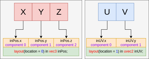
分量指派
规范详细地解释了分量指派的细节,这里只做简单描述。
填写分量
VkVertexInputAttributeDescription中的每个location都有 4 个分量,正如上面的示例,当着色器输入的分量较少时,会丢弃format多余的分量。
VK_FORMAT_R32G32B32_SFLOAT有 3 个分量,而 vec2只有 2 个分量。
如果是相反的情况,规范指出:
如果格式不包含 G、B 或 A 分量,对于非 64 位数据类型的属性,将用 (0,0,1) 填充(根据格式使用 1.0f 或整数 1)。
这意味着:
layout(location = 0) in vec3 inPos;
layout(location = 1) in uvec2 inUV;

上面的例子将填充内容成这样:
layout(location = 0) in vec4 inPos;
layout(location = 1) in uvec4 inUV;
